Just chillin
By Daniel Samson, CO-AUTHORED-BY: CLAUDE OPUS 4.8 <NOREPLY@ANTHROPIC.COM> · 2026-06-15
In the last part I laid out the problem: the rack runs warm, the server fans are loud, and I needed a smarter way to move air through the cabinet without it sounding like a jet engine at 2am. This post covers the next step — sorting out the fan controller hardware.
FanPico: not reinventing the wheel
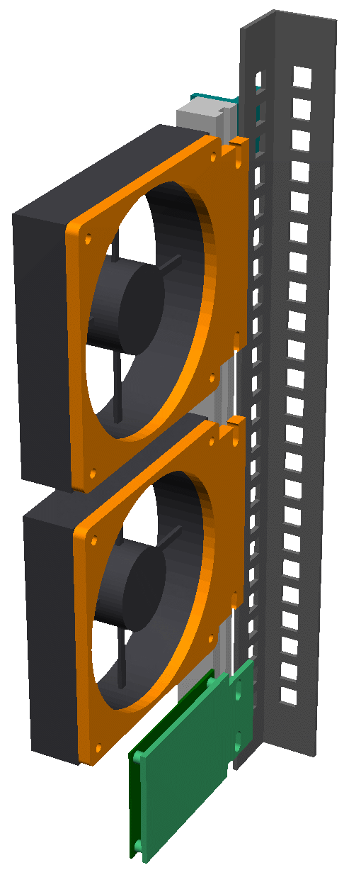
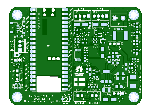
My first instinct was to build something from scratch — a Pico, some MOSFETs, a bit of code. Then I found FanPico and immediately abandoned that plan. The FANPICO-0200 board is a 2-channel PWM fan controller built around the Raspberry Pi Pico. Two fan outputs, temperature sensing inputs, 1-Wire header, clean firmware — it's exactly what I needed. Why spend a weekend debugging a rats-nest of wires when someone's already designed a proper PCB?
Ordering from PCBWay
PCBWay already has a shared project page for the FANPICO-0200 — here — so you can add it straight to your cart without uploading anything yourself. I still had to go through the Gerber layer names dialog, though, to make sure PCBWay mapped each file to the correct copper layer. Here's how I filled it in:
L1 → F.Cu (top copper) — file
fanpico-F_Cu.gtlL2 → In1.Cu (inner 1) — file
fanpico-In1_Cu.g2L3 → In2.Cu (inner 2) — file
fanpico-In2_Cu.g3L4 → B.Cu (bottom copper) — file
fanpico-B_Cu.gbl
After that it was pretty mechanical: selected assembly, chose how many boards I needed, picked delivery options, hit Calculate, reviewed the quote, and added to cart. PCBWay reviewed the order before it went through — there's a short wait while they sanity-check everything — and then it was confirmed and on its way.
Next up: parts arrive, things get soldered, and we find out whether the fan curve I've got in my head actually works in the real world.